Saturday, February 18, 2023

Section 33–5 Optical activity

 (Optical rotation / Optical rotatory power / Optical rotatory dispersion)


In this section, Feynman demonstrates the concept of optical activity using a transmission cell containing corn syrup and two polaroid sheets. This demonstration could be analyzed from the perspective of optical rotation, optical rotatory power, and optical rotatory dispersion.


1. Optical rotation:

“Such a substance may show an interesting effect called optical activity, whereby as linearly polarized light passes through the substance, the direction of polarization rotates about the beam axis (Feynman et al., 1963, p. 33–6).”


Feynman defines optical activity as an interesting effect whereby the direction of polarization rotates about the beam axis if linearly polarized light passes through a substance. This definition is imprecise because optical activity is also known as the ability of a substance that can cause optical rotation, circular dichroism*, and rotatory dispersion. However, we can define optical rotation in terms of three perspectives: (1) polarization: the rotation of the plane of polarization of light through a substance; (2) asymmetrical molecules: the presence of chiral molecules (or optical isomer) that do not have a plane of symmetry, i.e., the molecule is not the same as its mirror image; (3) interaction: the two opposite circularly polarized light in the substance would be out of phase after interacting with the molecules’ electrons.


*Optical rotation and circular dichroism can be formulated using the real and imaginary parts of the refractive index of an optically active substance, with optical rotation being related to the real part and circular dichroism being related to the imaginary part.


“Suppose all of the molecules in the substance are the same, i.e., none is a mirror image of any other. Such a substance may show an interesting effect called optical activity…… (Feynman et al., 1963, p. 33–6).”


Note that the optical rotation phenomenon is not necessarily observed unless all of the molecules in the substance are the same, e.g., either all molecules are right-handed or left-handed. That is, it depends on the optical purity (or enantiomeric excess) of a mixture of asymmetric molecules. For example, a 50:50 mixture of left and right-handed isomers cannot rotate the plane of polarization because the opposite effects of right-handed or left-handed molecules cancel each other out. On the other hand, an optical purity of 50% means that it is a 75:25 mixture of left and right-handed isomers. In general, the observed optical rotation of the mixture of asymmetric molecules is dependent on the nature of the molecules or its optical rotatory power.


2. Optical rotatory power:

“… the existence of optical activity and the sign of the rotation are independent of the orientation of the molecules (Feynman et al., 1963, p. 33–6).”


Feynman did not specifically say the sign of the rotation is independent of the orientation of the molecules. Some may interpret the statement as right and left-handedness of the molecules result in the same optical rotation. Historically, Pasteur recognized the phenomenon of dissymmetry, i.e., the handedness of the molecules determines their optical rotatory power. Although the amount of optical rotation is dependent on the angular orientation of the molecules, the sign will remain the same if they have the same handedness. Thus, the above sentence highlighted in yellow pertaining to the molecules’ orientation could be changed to “the sign of the rotation does not depend on the angular orientation of the molecules (without changing the left-right orientation).”


“When a light beam linearly polarized along the y-direction falls on this molecule, the electric field will drive charges up and down the helix, thereby generating a current in the y-direction and radiating an electric field Ey polarized in the y-direction (Feynman et al., 1963, p. 33–6).”

Feynman’s discussion of optical rotation may not be the better way to understand how the plane of polarization is rotated when a linearly polarized light propagates along an optically active substance. Alternatively, Fresnel (1822) explains that a linearly polarized light entering the substance is split into left and right circularly polarized light (or a superposition of R- and L-states). In essence, two opposite circularly polarized lights can move with different velocities such that there is a relative phase difference between them depending on the distance moved. Then, the two circularly polarized lights form a plane polarized light whose plane of polarization has been rotated when they emerge from the substance. Fresnel’s explanation is based on the assumption that a simple harmonic motion can be considered as a resultant of two opposite circular motions of the same frequency.


“However, if we consider the x-components of the electric field arriving at z = z2, we see that the field radiated by the current at z = z1+A and the field radiated from z = z1 arrive at z2 separated in time by the amount A/c, and thus separated in phase by π+ωA/c. Since the phase difference is not exactly π, the two fields do not cancel exactly, and we are left with a small x-component in the electric field...  (Feynman et al., 1963, p. 33–6).”


Feynman’s explanation using the phase difference of π+ωA/c (=π+ωt) is a simplification that does not include the generation of a magnetic field and it may seem to lead to nowhere. This is because Feynman elaborates that “jye-iwa/c - jyeiwa/c @ (i2wa/c)jy,” (Fig 1) but it is omitted in the text during the editing. However, the optically active substance may be a mix of left- or right-handed molecules and we can idealize a linearly polarized light as a superposition of two orthogonal states of circular polarization. Therefore, we can deduce the optical rotatory power of the substance using the phase difference formula: (nL – nR)pd/l. It can be shown that a small difference between the two refractive indices can result in a large optical rotation.

Fig 1 (Source: https://www.feynmanlectures.caltech.edu/Photos1_toc.html)
 

3. Optical rotatory dispersion:

“Corn syrup is a common substance which possesses optical activity. The phenomenon is easily demonstrated with a polaroid sheet to produce a linearly polarized beam, a transmission cell containing corn syrup, and a second polaroid sheet to detect the rotation of the direction of polarization as the light passes through the corn syrup (Feynman et al., 1963, p. 33–7).”


It is unclear why the above sentences on the demonstration involving the corn syrup are shifted to the end of the section. Feynman describes this demonstration before explaining the concept of optical activity. In the Audio Recordings** [34 min: 10 sec] of this lecture, Feynman says: “here we have the stuff which consists of Karo corn syrup mixed with water… Then I think you can see in here for those who are at least here at right angle to the thing: interesting spiral colors. Now the reason for this is really a combination of two phenomena at the same time, three in fact.” The observation of spiral colors may be termed optical rotatory dispersion which refers to the variation of optical rotation of a substance with respect to the wavelength of light. The three phenomena may include optical rotation (circular birefringence), circular dichroism, and rotatory dispersion.

**The Feynman Lectures Audio Collection: https://www.feynmanlectures.caltech.edu/flptapes.html


In the Audio recordings [35:55], Feynman elaborates: “also, of course, the colors which come out from the other end is polarized if we turn the polarizer we should get different colors…… The effect is different for a different color. So the blue and red and so on have their spirals (each is chromatic)…...” In essence, shorter wavelengths (e.g., violet) are rotated more than longer wavelengths (e.g., red) per unit of distance. Mathematically, the rotatory dispersion may be modeled using Drude’s formula a = A/(l2 - l02) where A is the rotation constant, l0 is the dispersion constant and l is the wavelength of light (Nixon, & Hughes, 2017). An experimental setup for optical rotation and optical rotatory dispersion involving corn syrup is shown below (Fig 2). Perhaps Feynman could have ended the section by concluding similar experiments have important implications in Biology, Chemistry, and Pharmacy.


Fig 2 An experimental setup (Nixon, & Hughes, 2017)

Review Questions:

1. How would you define an optically active substance?

2. Would you adopt Feynman’s mathematical explanation of optical rotation or Fresnel’s concept of circularly polarized light?

3. Does Feynman’s demonstration involve the phenomena of circular birefringence, circular dichroism, and rotatory dispersion (or interference, polarization, and dispersion)?


The moral of the lesson: optical activity is a phenomenon in which a substance rotates the plane of polarization of light, and this rotation can be characterized by its optical rotatory power and its variation with respect to the wavelength of light, which is known as optical rotatory dispersion.


References:

1. Feynman, R. P., Leighton, R. B., & Sands, M. (1963). The Feynman Lectures on Physics, Vol I: Mainly mechanics, radiation, and heat. Reading, MA: Addison-Wesley.

2. Fresnel, A. (1822). Mémoire sur la double réfraction que les rayons lumineux éprouvent en traversant les aiguilles de cristal de roche suivant des directions parallèles à l’axe. Oeuvres, 1, 731-751.

3. Nixon, M., & Hughes, I. G. (2017). A visual understanding of optical rotation using corn syrup. European Journal of Physics, 38(4), 045302.

Monday, February 6, 2023

Section 33–4 Polarizers

 (Malus’ polarization law / Three polarizer paradox / Brewster’s angle)


In this section, Feynman discusses Malus’ polarization law, three polarizer paradox (or Dirac’s polarization paradox), and Brewster’s angle. It could be titled “polarization by reflection and polarizers” instead of polarizers because the previous sections are about “polarization by scattering of light” and “polarization by birefringence.”


1. Malus’ polarization law:

“The energy which passes through the polaroid, i.e., the intensity of the light, is proportional to the square of cos θ. Cos2 θ, then, is the intensity transmitted when the light enters polarized at an angle θ to the pass direction (Feynman et al., 1963, p. 33–5).”


Malus’ law states that the intensity of a plane-polarized light (I) that passes through a polarizer varies with the square of the cosine of the angle (q) between the light’s initial polarization and the transmission axis of the polarizer in accordance with I = I0cos2 q, where I0 is the initial intensity. This is an idealization because Malus could not verify the law using an accurate light intensity meter. This law was published in 1809, but Nicol prism (the first easily usable polarizer) was invented in 1828. On the other hand, Malus’ works on polarization were based on the corpuscular theory of light. Thus, Malus’ polarization law did not have a correct theoretical basis and adequate empirical support, but it involves the assumption of an ideal (or perfect) polarizer.


Perhaps Feynman could have included a definition of an ideal polarizer or real polarizer. For example, one may define an ideal polarizer as an optical device: (1) whose intensity is reduced in accordance with Malus’ Law; (2) which may effectively rotate linearly polarized light in a direction parallel to its transmission axis. On the contrary, a real polarizer can be defined in terms of polarization efficiency and extinction ratio. Specifically, a real polarizer may transmit about 80% of light polarized in one direction and less than 1% of light polarized in the direction at right angles to it (Born & Wolf, 1980). In the real world, we should not expect a completely linear polarized light because the needle-like molecules in the polarizer are not infinitely thin, but have a small radius.


Note: In the Audio Recordings [32 min: 15 sec] of this lecture*, Feynman says: “… The polaroid is not perfect, it’s not exactly zero.”

*The Feynman Lectures Audio Collection: https://www.feynmanlectures.caltech.edu/flptapes.html


2. Three polarizer paradox:

“An interesting paradox is presented by the following situation. We know that it is not possible to send a beam of light through two polaroid sheets with their axes crossed at right angles. But if we place a third polaroid sheet between the first two, with its pass axis at 45o to the crossed axes, some light is transmitted. We know that polaroid absorbs light, it does not create anything. Nevertheless, the addition of a third polaroid at 45o allows more light to get through (Feynman et al., 1963, p. 33–5).”


The paradox presented by Feynman is sometimes known as Dirac’s polarization paradox. The crux of the paradox is related to “polaroid absorbs light, it does not create anything.” In many definitions of a polarizer, we may find words, such as “filter”, “block,” or “completely absorb.” For instance, a polarizer is an optical filter that lets light waves of a specific polarization pass through while blocking light waves of other polarizations (Source: Wikipedia). From the perspective of an ideal polarizer, one may explain that the polarizer does not only absorb light, but it effectively rotates the direction of polarization of light. The paradox may be resolved by calculating the final intensity of light using Malus’ polarization law and taking into account the order of the three polarizers tilted at different angles.


In Feynman’s words, “[w]e know that polaroid absorbs light, it does not create anything.” This statement is perhaps deliberately misleading in order to create an apparent paradox. From the perspective of a real polarizer, there is really no paradox because this polarizer can transmit light, absorb light, reflect light, and effectively rotate the plane polarization of light. (We can see the real polarizer because it does reflect light, i.e., it does not simply filter light.) More important, a real polarizer does not completely obey Malus’ polarization law and it is wavelength dependent. Strictly speaking, it is still possible to send a beam of light through two polarizers with their axes crossed at right angles.


Although the three polarizers paradox is attributed to Dirac, his main concern was the interaction of a photon with a polarizer (tourmaline). As he was trying to understand the experimental results from the perspective of a photon, Dirac (1947) writes, “[i]f one repeats the experiment a large number of times, one will find the photon on the back side in a fraction sin2 α of the total number of times. Thus we may say that the photon has a probability sin2 α of passing through the tourmaline [polarizer] and appearing on the back side polarized perpendicular to the axis and a probability cos2 α of being absorbed. These values for the probabilities lead to the correct classical results for an incident beam containing a large number of photons (p. 6).” In essence, the experimental setup forces the photon to be completely into the state of perpendicular polarization or parallel polarization. It provides a quantum mechanical perspective on the paradox.


3. Brewster’s angle:

“It was discovered empirically by Brewster that light reflected from a surface is completely polarized if the reflected beam and the beam refracted into the material form a right angle. (Feynman et al., 1963, p. 33–5).”


We may define Brewster’s angle (or polarizing angle) in terms of three perspectives: (1) s-polarized light: when the incident light is polarized normal to the plane of incidence, the reflected light is maximally polarized at the polarizing angle; it means that light can be polarized by reflection; (2) p-polarized light: when the incident light is polarized parallel to the plane of incidence, there is “no reflection” of p-polarized light; it indicates that light is a transverse wave; (3) unpolarized light: the reflected light and refracted light form a right angle; it leads to the equation tan qB = n (specifically, tan qB = n2/n1) in which n is the refractive index of the medium. Perhaps Feynman could have used the phrase maximally polarized (instead of completely polarized) because of multiple interactions of light with the reflection surface.


“From Fig. 33–4 it is clear that only oscillations normal to the paper can radiate in the direction of reflection, and consequently the reflected beam will be polarized normal to the plane of incidence. If the incident beam is polarized in the plane of incidence, there will be no reflected light (Feynman et al., 1963, p. 33–6).”


In a sense, the phrase “it is clear” may be misleading because some explanations are needed to understand why the reflected light will be polarized normal to the plane. Firstly, some may need an explanation of how oscillating charges produce a donut-shaped radiation whereby there is no radiation along the axis of oscillation. Secondly, the main contribution of reflected light comes from a small critical region at the interface of the reflection surface where light can travel shortest distances to reach an observer (Fermat’s principle of least action). Thirdly, there is no reflected light at Brewster’s angle unless light is a longitudinal wave. That is, charges oscillating at the interface of two media that produce reflected light and refracted light “should” have the same polarization as shown below. However, the surface of reflection is not perfectly smooth and we may describe the reflected light at Brewster’s angle as not exactly zero or it is minimally polarized.


In his seminal paper on the blue sky, Tyndall (1869) writes: “the polarization of the beam by the incipient cloud has thus far proved to be absolutely independent of the polarizing-angle. The law of Brewster does not apply to matter in this condition, and it rests with the undulatory theory to explain why. Whenever the precipitated particles are sufficiently fine, no matter what the substance forming the particles may be, the direction of maximum polarization is at right angles to the illuminating beam…” Rayleigh cited Tyndall’s words and responded, “I venture to think that the difficulty is entirely imaginary, and is caused mainly by misuse of the word reflection (Strutt, 1871, p.107).” Interestingly, Feynman provides a good explanation of the word reflection: “this so-called reflected light is not simply that the incident beam is reflected; our deeper understanding of this phenomenon tells us that the incident beam drives an oscillation of the charges in the material, which in turn generates the reflected beam.” However, Brewster’s angle could be related to the maximally polarized light scattered at 90o which is briefly discussed in Section 33.2.


Review Questions:

1. How would you define an ideal polarizer or real polarizer?

2. Do you agree with Feynman that “it is not possible to send a beam of light through two polaroid sheets with their axes crossed at right angles”?

3. (a) How could one tell the absolute direction of polarization from a piece of polaroid? (Source: Page 212 of Surely You’re Joking, Mr. Feynman!)

(b) How would you explain Brewster’s angle pertaining to the reflection on a grain of salt?


The moral of the lesson: The concept of Malus’ polarization law, Dirac’s polarization paradox, and Brewster’s angle may help us to take a better picture using a polarizer filter as shown below.


References:

1. Born, M., & Wolf, E. (1980). Principles of optics: electromagnetic theory of propagation, interference, and diffraction of light (6th ed.). New York: Pergamon.

2. Dirac, P. A. M. (1981). The principles of quantum mechanics. London: Oxford university press.

3. Feynman, R. P. (1997). Surely You’re Joking, Mr. Feynman! : Adventures of a Curious Character. New York: Norton.

4. Feynman, R. P., Leighton, R. B., & Sands, M. (1963). The Feynman Lectures on Physics, Vol I: Mainly mechanics, radiation, and heat. Reading, MA: Addison-Wesley.

5. Strutt, J. W. (1871). XV. On the light from the sky, its polarization and colour. The London, Edinburgh, and Dublin Philosophical Magazine and Journal of Science, 41(271), 107-120. 

6. Tyndall, J. (1869). On the blue colour of the sky, and on the polarization of light. Phil. M., (4), 37, 384-394.

Saturday, January 14, 2023

Section 33–3 Birefringence

(Birefringent crystals / Birefringent waveplate / Induced birefringence)


In this section, Feynman discusses birefringent crystals, birefringent waveplate, and induced birefringence. To be consistent, it could also be titled “polarization by birefringence” or “polarization by absorption” because the previous section is about “polarization by scattering of light” and the next section is related to “polarization by reflection.”


1. Birefringent crystals:

“Let us call the direction of the axes of the molecules the optic axis. When the polarization is in the direction of the optic axis the index of refraction is different than it would be if the direction of polarization were at right angles to it (Feynman et al., 1963, p. 33–3).”


Feynman defines optic axis as the direction of the axes of the molecules whereby the refractive index is different than it would be if the direction of polarization were at right angles to it. However, a more precise definition of the optic axis of a birefringent crystal should include atomic arrangement, refractive index, and velocities of light. Firstly, the optic axis is the axis of symmetry with respect to the arrangement of atoms, i.e., it lies in a plane of symmetry for crystals with certain symmetries. Secondly, light moving through this axis would feel the same refractive index (or binding force in x and y direction) independent of the polarization direction. Thirdly, the velocities of ordinary and extraordinary rays are different in all directions of light propagation except in the optic axis. In other words, the optic axis is not a line, but a direction whereby light can pass through the crystal without birefringence (double refraction).


“Such a substance is called birefringent. It has two refrangibilities, i.e., two indexes of refraction, depending on the direction of the polarization inside the substance (Feynman et al., 1963, p. 33–3).”


Feynman explains that a birefringent substance has two refractive indexes (or indices) that depend on the polarization direction inside the substance. One may clarify that birefringence is a phenomenon of two refracted light rays in an optically anisotropic medium where the interaction of light (or refractive index) depends on the polarization state and direction of propagation of light. In essence, it is a splitting of incident light into two parallel rays of perpendicular polarization through a uniaxial (single optic axis) crystal provided the light is not parallel to the optic axis. Specifically, hexagonal, and tetragonal crystals have two refractive indices (uniaxial), but orthorhombic, monoclinic, and triclinic crystals have three refractive indices (biaxial) (See Fig. 1). Mathematically, birefringence is a measure of the difference between two refractive indices for two different directions of light propagation.

Fig. 1

Source: https://viva.pressbooks.pub/petrology/chapter/2-8-interference-figures-part-2/

Note: In the UK, there are seven categories of crystal systems: cubic, tetragonal, hexagonal, trigonal, orthorhombic, monoclinic, and triclinic. In the US, there are six categories because the trigonal system is considered to be a subset of the hexagonal system.


“Such a substance is called birefringent. It has two refrangibilities, i.e., two indexes of refraction, depending on the direction of the polarization inside the substance (Feynman et al., 1963, p. 33–3).”


Instead of using the phrase direction of the polarization, we may state the optic axis inside the birefringent crystal. Furthermore, natural light has two linear polarizations that may result in ordinary and extraordinary rays. For example, we can cut and polish a calcite crystal so that its optic axis is normal to its front and back surfaces (Hecht, 2002). If the incident light is normal to the front surface of the crystal, it will not be split into ordinary and extraordinary rays. If we cut and polish the calcite crystal so that its optic axis is in the plane of the front surface, we can observe ordinary and extraordinary rays because the light would feel two different refractive indices within the crystal. Feynman discusses ordinary and extraordinary rays at the end of the lecture, but some physics teachers may not agree with this teaching sequence.


2. Birefringent waveplate:

“Since the x- and y-polarizations travel with different velocities, their phases change at a different rate as the light passes through the substance... If the thickness of the plate is just right to introduce a 90o phase shift between the x- and y-polarizations, as in Fig. 33–2(c), the light will come out circularly polarized. Such a thickness is called a quarter-wave plate, because it introduces a quarter-cycle phase difference between the x- and the y-polarizations (Feynman et al., 1963, p. 33–3).”


According to Feynman, a quarter-wave plate is a plate whose thickness is just right to introduce a 90o phase shift between the x- and y-polarizations. In general, waveplates are made of birefringent materials that have a difference in refractive index between two orthogonal principal axes, commonly known as fast axis and slow axis. The fast axis of the waveplate has a lower refractive index, resulting in a faster velocity for polarized light moving in this direction. Conversely, the slow axis has a higher refractive index, resulting in a slower velocity for light moving parallel to this axis. In a positive uniaxial crystal, the fast axis (ordinary ray) is perpendicular to the optic axis, while the slow axis (extraordinary ray) coincides with the optic axis. However, this section is potentially confusing because of many terms related to the axis: molecular axis, axis of the polaroid, axis of linearly polarized light, beam axis, pass axes of the polaroid sheets, and optic axes of the cellophane.


“Polaroid, which we will discuss later in more detail, has the useful property that it transmits light that is linearly polarized parallel to the axis of the polaroid with very little absorption, but light polarized in a direction perpendicular to the axis of the polaroid is strongly absorbed (Feynman et al., 1963, p. 33–4).”


Polarization by absorption: A polaroid transmits polarized light that is parallel to the polaroid’s axis and absorbs polarized light that is perpendicular to the polaroid’s axis. The absorption of light is dependent on the molecular structure (e.g., needle-like crystals or long molecular chains) of the polarizer because the electrons oscillate more easily in the longer parts of the molecules. The oscillation of electrons along the long molecular chains may result in collisions with other molecules and re-emission of light in all directions. In the Audio Recordings* [23 min: 00 sec] of this lecture, Feynman says: “Different colors have different indices,” but this sentence could be edited instead of omitted. For example, different light frequencies have different refractive indices and absorption bands depending on the optic axis and direction of light propagation (see Fig. 2 below).

*The Feynman Lectures Audio Collection: https://www.feynmanlectures.caltech.edu/flptapes.html

Fig. 2 (Hecht, 2002)

3. Induced birefringence:

“So when a stress is applied to certain plastics, they become birefringent, and one can see the effects of the birefringence by passing polarized light through the plastic (Feynman et al., 1963, p. 33–5).”


According to Feynman, we can see the effects of the birefringence by passing polarized light through certain plastics when a stress is applied. We may explain stress-induced birefringence (photoelastic effect) from the perspective of random polymer chains, optic axis, and operating procedure. Firstly, the applied stress (tension or compression) aligns the random polymer chains and inherent uniaxial anisotropy (related to refractive indices) of the chain structure. Secondly, the optic axis is in the direction of the applied stress and the induced birefringence is proportional to the stress. Last but not least, the optic axis of a stressed sample should be oriented at 45o with respect to the polarizer and analyzer such that the maximum brightness for the sample can be observed.


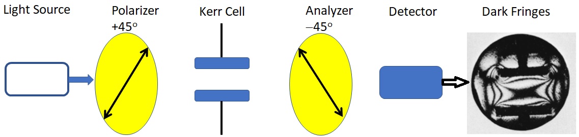
“So we have an electrical switch for light, which is called a Kerr cell. This effect, that an electric field can produce birefringence in certain liquids, is called the Kerr effect (Feynman et al., 1963, p. 33–5).”


Feynman relates the Kerr effect to an electric field that can induce birefringence in certain liquids. Feynman’s explanation could be elaborated from the perspective of randomly oriented molecules, optic axis, and operating procedure. Simply put, light is passed through a liquid or glass (randomly arranged and oriented molecules) that is contained in a Kerr cell. Kerr effect means that an isotropic material can behave like a uniaxial crystal when a voltage is applied such that an optical axis is made parallel to the electric field. In the Audio Recordings* [26 min: 30 sec] of this lecture, Feynman says: “I put the birefringence at 45 degrees and I change it and so on and the light comes through,” but this sentence could be edited and illustrated by the diagram as shown below (see Fig. 3). However, induced birefringence is a “symmetry breaking” phenomenon that may also be thermally induced, flow-induced, or laser-induced.


Fig. 3

*The Feynman Lectures Audio Collection: https://www.feynmanlectures.caltech.edu/flptapes.html


Review Questions:

1. How would you define the optic axis of a birefringent crystal?

2. Would you describe a birefringent waveplate using terms such as molecular axis, axis of the polaroid, beam axis, pass axes, and optic axes (or fast axis and slow axis)?

3. How would you explain the optic axis of a sample should be oriented at 45o with respect to the polarizer and analyzer such that induced birefringence can be observed?


The moral of the lesson: a birefringent substance, natural or induced, is due to the presence of an optic axis (axis of symmetry), whereby the refractive index is dependent on the direction of light propagation.


References:

1. Feynman, R. P., Leighton, R. B., & Sands, M. (1963). The Feynman Lectures on Physics, Vol I: Mainly mechanics, radiation, and heat. Reading, MA: Addison-Wesley.

2. Hecht, E. (2002). Optics (4th edition). San Francisco: Addison Wesley.