Saturday, January 14, 2023

Section 33–3 Birefringence

(Birefringent crystals / Birefringent waveplate / Induced birefringence)


In this section, Feynman discusses birefringent crystals, birefringent waveplate, and induced birefringence. To be consistent, it could also be titled “polarization by birefringence” or “polarization by absorption” because the previous section is about “polarization by scattering of light” and the next section is related to “polarization by reflection.”


1. Birefringent crystals:

“Let us call the direction of the axes of the molecules the optic axis. When the polarization is in the direction of the optic axis the index of refraction is different than it would be if the direction of polarization were at right angles to it (Feynman et al., 1963, p. 33–3).”


Feynman defines optic axis as the direction of the axes of the molecules whereby the refractive index is different than it would be if the direction of polarization were at right angles to it. However, a more precise definition of the optic axis of a birefringent crystal should include atomic arrangement, refractive index, and velocities of light. Firstly, the optic axis is the axis of symmetry with respect to the arrangement of atoms, i.e., it lies in a plane of symmetry for crystals with certain symmetries. Secondly, light moving through this axis would feel the same refractive index (or binding force in x and y direction) independent of the polarization direction. Thirdly, the velocities of ordinary and extraordinary rays are different in all directions of light propagation except in the optic axis. In other words, the optic axis is not a line, but a direction whereby light can pass through the crystal without birefringence (double refraction).


“Such a substance is called birefringent. It has two refrangibilities, i.e., two indexes of refraction, depending on the direction of the polarization inside the substance (Feynman et al., 1963, p. 33–3).”


Feynman explains that a birefringent substance has two refractive indexes (or indices) that depend on the polarization direction inside the substance. One may clarify that birefringence is a phenomenon of two refracted light rays in an optically anisotropic medium where the interaction of light (or refractive index) depends on the polarization state and direction of propagation of light. In essence, it is a splitting of incident light into two parallel rays of perpendicular polarization through a uniaxial (single optic axis) crystal provided the light is not parallel to the optic axis. Specifically, hexagonal, and tetragonal crystals have two refractive indices (uniaxial), but orthorhombic, monoclinic, and triclinic crystals have three refractive indices (biaxial) (See Fig. 1). Mathematically, birefringence is a measure of the difference between two refractive indices for two different directions of light propagation.

Fig. 1

Source: https://viva.pressbooks.pub/petrology/chapter/2-8-interference-figures-part-2/

Note: In the UK, there are seven categories of crystal systems: cubic, tetragonal, hexagonal, trigonal, orthorhombic, monoclinic, and triclinic. In the US, there are six categories because the trigonal system is considered to be a subset of the hexagonal system.


“Such a substance is called birefringent. It has two refrangibilities, i.e., two indexes of refraction, depending on the direction of the polarization inside the substance (Feynman et al., 1963, p. 33–3).”


Instead of using the phrase direction of the polarization, we may state the optic axis inside the birefringent crystal. Furthermore, natural light has two linear polarizations that may result in ordinary and extraordinary rays. For example, we can cut and polish a calcite crystal so that its optic axis is normal to its front and back surfaces (Hecht, 2002). If the incident light is normal to the front surface of the crystal, it will not be split into ordinary and extraordinary rays. If we cut and polish the calcite crystal so that its optic axis is in the plane of the front surface, we can observe ordinary and extraordinary rays because the light would feel two different refractive indices within the crystal. Feynman discusses ordinary and extraordinary rays at the end of the lecture, but some physics teachers may not agree with this teaching sequence.


2. Birefringent waveplate:

“Since the x- and y-polarizations travel with different velocities, their phases change at a different rate as the light passes through the substance... If the thickness of the plate is just right to introduce a 90o phase shift between the x- and y-polarizations, as in Fig. 33–2(c), the light will come out circularly polarized. Such a thickness is called a quarter-wave plate, because it introduces a quarter-cycle phase difference between the x- and the y-polarizations (Feynman et al., 1963, p. 33–3).”


According to Feynman, a quarter-wave plate is a plate whose thickness is just right to introduce a 90o phase shift between the x- and y-polarizations. In general, waveplates are made of birefringent materials that have a difference in refractive index between two orthogonal principal axes, commonly known as fast axis and slow axis. The fast axis of the waveplate has a lower refractive index, resulting in a faster velocity for polarized light moving in this direction. Conversely, the slow axis has a higher refractive index, resulting in a slower velocity for light moving parallel to this axis. In a positive uniaxial crystal, the fast axis (ordinary ray) is perpendicular to the optic axis, while the slow axis (extraordinary ray) coincides with the optic axis. However, this section is potentially confusing because of many terms related to the axis: molecular axis, axis of the polaroid, axis of linearly polarized light, beam axis, pass axes of the polaroid sheets, and optic axes of the cellophane.


“Polaroid, which we will discuss later in more detail, has the useful property that it transmits light that is linearly polarized parallel to the axis of the polaroid with very little absorption, but light polarized in a direction perpendicular to the axis of the polaroid is strongly absorbed (Feynman et al., 1963, p. 33–4).”


Polarization by absorption: A polaroid transmits polarized light that is parallel to the polaroid’s axis and absorbs polarized light that is perpendicular to the polaroid’s axis. The absorption of light is dependent on the molecular structure (e.g., needle-like crystals or long molecular chains) of the polarizer because the electrons oscillate more easily in the longer parts of the molecules. The oscillation of electrons along the long molecular chains may result in collisions with other molecules and re-emission of light in all directions. In the Audio Recordings* [23 min: 00 sec] of this lecture, Feynman says: “Different colors have different indices,” but this sentence could be edited instead of omitted. For example, different light frequencies have different refractive indices and absorption bands depending on the optic axis and direction of light propagation (see Fig. 2 below).

*The Feynman Lectures Audio Collection: https://www.feynmanlectures.caltech.edu/flptapes.html

Fig. 2 (Hecht, 2002)

3. Induced birefringence:

“So when a stress is applied to certain plastics, they become birefringent, and one can see the effects of the birefringence by passing polarized light through the plastic (Feynman et al., 1963, p. 33–5).”


According to Feynman, we can see the effects of the birefringence by passing polarized light through certain plastics when a stress is applied. We may explain stress-induced birefringence (photoelastic effect) from the perspective of random polymer chains, optic axis, and operating procedure. Firstly, the applied stress (tension or compression) aligns the random polymer chains and inherent uniaxial anisotropy (related to refractive indices) of the chain structure. Secondly, the optic axis is in the direction of the applied stress and the induced birefringence is proportional to the stress. Last but not least, the optic axis of a stressed sample should be oriented at 45o with respect to the polarizer and analyzer such that the maximum brightness for the sample can be observed.


“So we have an electrical switch for light, which is called a Kerr cell. This effect, that an electric field can produce birefringence in certain liquids, is called the Kerr effect (Feynman et al., 1963, p. 33–5).”


Feynman relates the Kerr effect to an electric field that can induce birefringence in certain liquids. Feynman’s explanation could be elaborated from the perspective of randomly oriented molecules, optic axis, and operating procedure. Simply put, light is passed through a liquid or glass (randomly arranged and oriented molecules) that is contained in a Kerr cell. Kerr effect means that an isotropic material can behave like a uniaxial crystal when a voltage is applied such that an optical axis is made parallel to the electric field. In the Audio Recordings* [26 min: 30 sec] of this lecture, Feynman says: “I put the birefringence at 45 degrees and I change it and so on and the light comes through,” but this sentence could be edited and illustrated by the diagram as shown below (see Fig. 3). However, induced birefringence is a “symmetry breaking” phenomenon that may also be thermally induced, flow-induced, or laser-induced.
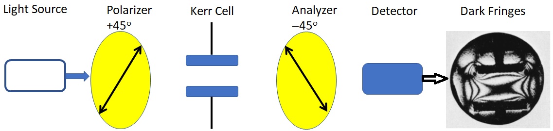
 

Fig. 3

*The Feynman Lectures Audio Collection: https://www.feynmanlectures.caltech.edu/flptapes.html


Review Questions:

1. How would you define the optic axis of a birefringent crystal?

2. Would you describe a birefringent waveplate using terms such as molecular axis, axis of the polaroid, beam axis, pass axes, and optic axes (or fast axis and slow axis)?

3. How would you explain the optic axis of a sample should be oriented at 45o with respect to the polarizer and analyzer such that induced birefringence can be observed?


The moral of the lesson: a birefringent substance, natural or induced, is due to the presence of an optic axis (axis of symmetry), whereby the refractive index is dependent on the direction of light propagation.


References:

1. Feynman, R. P., Leighton, R. B., & Sands, M. (1963). The Feynman Lectures on Physics, Vol I: Mainly mechanics, radiation, and heat. Reading, MA: Addison-Wesley.

2. Hecht, E. (2002). Optics (4th edition). San Francisco: Addison Wesley.

Thursday, December 22, 2022

Section 33–2 Polarization of scattered light

(Rayleigh scattering / Random polarizations / Lateral scattering)


In this section, Feynman briefly discusses Rayleigh scattering, random polarizations, and lateral scattering. In the Audio Recordings* [14 min: 05 sec], Feynman says something like: “If there is a beam of light like the Sun shining on the air, it will have an electric field say this way or in this way, it will change if it is unpolarized. If we stand down over here, we see that when I am doing the time that it is polarized in this direction, the wave will be generated this way (scattered wave) by the motion of charge in the air. On the other hand, when the light is polarised this way during the time that it is doing that during the unpolarised (averaging in space) because the current is in the line of sight, so there is no field generated in the eye, when it is this way, all the field would be generated in the eye is polarised up and down.” This section is heavily edited, but there could be some diagrams to explain the polarization of scattered light. It could also be titled “Polarization by scattering of light” because the next section is about “Polarization by absorption.”


*The Feynman Lectures Audio Collection: https://www.feynmanlectures.caltech.edu/flptapes.html


1. Rayleigh Scattering:

“The first example of the polarization effect that we have already discussed is the scattering of light. Consider a beam of light, for example from the sun, shining on the air. The electric field will produce oscillations of charges in the air, and motion of these charges will radiate light with its maximum intensity in a plane normal to the direction of vibration of the charges (Feynman et al., 1963, p. 33-3).”


The term scattering refers to Rayleigh scattering, i.e., the absorption of light by a particle and the emission of light due to the particle’s oscillation. In other words, the electric field of the incoming light oscillates the electrons, and the oscillated electrons will emit scattered light (or secondary waves) in different directions. However, some may not be able to visualize the plane, normal to the direction of vibration of the charges, that has maximum intensity. Specifically, the radiation pattern due to the scattering of a single molecule has a doughnut (or donut) shape (see Fig. 1) and the intensity is zero along the direction of the oscillation of the charge. Strictly speaking, the intensity would not be zero because of multiple scattering and the air molecules are randomly oriented.

Fig. 1


We can deduce the radiation pattern of an oscillating charge to be doughnut-shaped using the third term of the Feynman-Heaviside expression of accelerated charge (equation 28.3). This helps to explain why Feynman says: “motion of these charges will radiate light with its maximum intensity in a plane normal to the direction of vibration of the charges.” To be precise, maximum intensity occurs at a horizontal plane if the charge is oscillating vertically. This radiation pattern is an idealization because the oscillation of the charge is not always along the same axis. In the real world, we may imagine the radiation pattern to be a rotatable doughnut about the direction of propagation of light (z-axis) and it is dependent on the linear polarization of light in the x-axis or y-axis.


2. Random polarizations:

The beam from the sun is unpolarized, so the direction of polarization changes constantly, and the direction of vibration of the charges in the air changes constantly (Feynman et al., 1963, p. 33-3).


Instead of saying “the beam from the Sun is unpolarized,” we may clarify that the wave packets emitted by the Sun are randomly polarized. Firstly, the term wave packet means a short oscillatory directional pulse that is emitted within a duration on the order of 10-8 s to 10-9 s. This corresponds to a state of atomic excitation (or a short-lived resonance phenomenon) whereby the excited atom spontaneously relaxes back to a lower state and loses the excitation energy. On the other hand, the Sun consists of a very large number of randomly oriented atomic emitters and the wave packets from the Sun are randomly polarized. Thus, the direction of polarization changes randomly and the direction of vibration of the charges in the air changes randomly (instead of changing constantly).


Perhaps Feynman could have mentioned there was a crisis in optics over the challenge to develop a general formula of randomly and partially polarized light. In 1852, Sir George Gabriel Stokes, Rayleigh’s optics teacher, proposed that any polarization state can be completely described by four measurable quantities or parameters. The four Stokes parameters are not dependent on a coordinate system, but they can be easily calculated or measured. For example, we can investigate the pulsar in the Crab Nebula using Stokes parameters and measuring its optical and radio-frequency radiation. (Feynman discusses the radiation emitted by the Crab Nebula in the next chapter.) However, some may argue whether linearly and circularly polarized light are special cases of elliptically polarized light from the perspective of Stokes parameters.


3. Lateral scattering:

“If we consider light scattered at 90o, the vibration of the charged particles radiates to the observer only when the vibration is perpendicular to the observer’s line of sight, and then light will be polarized along the direction of vibration (Feynman et al., 1963, p. 33-3).”


Fig. 2 (Source: https://byjus.com/physics/polarisation-by-scattering/)

It may not be clear why “Feynman” says the light will be polarized along the direction of vibration if it is scattered at 90o and the vibration is perpendicular to the observer’s line of sight. This could be illustrated using a diagram (see Fig. 2): Firstly, the scattered light rays that are parallel to the incoming light are completely unpolarised. Secondly, the light rays scattered at 90o are completely polarized because there is no polarized light that oscillates in the direction of the incoming light. (Based on the definition of polarized light, the electric field of incoming light and scattered light “cannot oscillate longitudinally” in the direction of propagation of light.) Thirdly, the scattered light rays in all other directions (between 0o and 90o) are partially polarized. To be precise, the light scattered at 90o is maximally polarized (instead of completely polarized) because of multiple and random scattering.


Fig. 3

The “light scattered at 90o” (lateral scattering) can occur at an infinite number of possible angles (Fig. 3). In general, the lateral scattering of light by a single molecule could be elaborated from the perspective of horizontally (x-direction) and vertically (y-direction) polarized light (Fig. 4). If the incoming light is moving in the z-direction and horizontally polarized, the light scattered in the y-direction (upward or downward) should remain as horizontally polarized. If the incoming light is moving in the z-direction and vertically polarized, the light scattered in the x-direction (toward or away from the observer) should remain vertically polarized. Although we can assume polarized light to have no longitudinal component, but this assumption is violated in a glass fiber (Junge et al., 2013).


Fig. 4

Review Questions:

1. How would you explain the oscillation of charges in the air radiates light with its maximum intensity in a plane normal to the direction of vibration of the charges?

2. Does the direction of vibration of the charges in the air change constantly (or randomly?) if the sunlight is unpolarized?

3. How would you explain the light is maximally polarized if it is scattered at 90o?


The moral of the lesson: Light rays are horizontally polarized along the entire horizon when the sun is high up in the sky at noon, but they are maximally polarized along the meridian that passes through the zenith during sunset (See Fig. 5).


Fig. 5

Note: In Chapter 36, Feynman elaborates: “The bee can tell, because the bee is quite sensitive to the polarization of light, and the scattered light of the sky is polarized.” In 1949, Karl von Frisch established that bees, through their perception of polarized light, are able to remember polarization patterns presented by the sky at different times of the day when the Sun is not visible. Karl von Frisch is awarded the Nobel Prize in Physiology or Medicine 1973 for explaining the waggle dance used by bees to communicate the location of food sources.


References:

1. Feynman, R. P. (1985). QED: The strange theory of light and matter. Princeton: Princeton University Press.

2. Feynman, R. P., Leighton, R. B., & Sands, M. (1963). The Feynman Lectures on Physics, Vol I: Mainly mechanics, radiation, and heat. Reading, MA: Addison-Wesley.

3. Junge, C., O’shea, D., Volz, J., & Rauschenbeutel, A. (2013). Strong coupling between single atoms and nontransversal photons. Physical review letters, 110(21), 213604.

Monday, November 14, 2022

Section 33–1 The electric vector of light

(Linearly polarized / Elliptically polarized / Unpolarized)


In this section, Feynman discusses linearly polarized light, elliptically polarized light, and unpolarized light.


1. Linearly polarized:

“Light is linearly polarized (sometimes called plane polarized) when the electric field oscillates on a straight line; Fig. 33–1 illustrates linear polarization (Feynman et al., 1963, p. 33–2).”


Feynman explains that light is linearly polarized (or plane polarized) provided its electric field oscillates on a straight line. Historically, Étienne-Louis Malus (1811) defines plane of polarization as the plane that contains the direction of propagation and the magnetic field. In the Audio Recordings* [9 min: 00 sec] of this lecture, Feynman says: “historically, they did not know which field is the right one,” i.e., the term plane of polarization is confusing due to the older literature. Thus, some physicists define plane of vibration using the orientation of electric field because most materials interact more strongly with electric fields as compared to magnetic fields. The plane of vibration is not definitely constant at any point, but if it rotates uniformly, the light may be described as circularly (or helically) polarized.


*The Feynman Lectures Audio Collection: https://www.feynmanlectures.caltech.edu/flptapes.html


“The motion in a straight line is a particular case corresponding to a phase difference of zero (or an integral multiple of Ï€); motion in a circle corresponds to equal amplitudes with a phase difference of 90o (or any odd integral multiple of Ï€/2) (Feynman et al., 1963, p. 33–1).”


We can define polarized light using E = (Acos qx)ei(kz - wt) x + (Asin qy)ei(kz - wt) y. According to Feynman, linearly polarized light is a special case corresponding to a phase difference Dq = qy − qx = nÏ€, n = 0, 1, 2, 3…; circularly polarized light corresponds to equal amplitudes with a phase difference of Ï€/2, 3Ï€/2, or equivalent. In addition, any linearly polarized light can be formed from two different circularly polarized lights because the “left-handed rotation” component can be canceled by the “right-handed rotation” component. In the Audio Recordings [11 min: 00 sec], Feynman says: “suppose we have a left-hand circular and right-hand circular… adding two circular polarized lights in phase and equal amplitude, we get linearly polarized light.” This explanation is edited and shifted to section 33-5: “any linear polarization can be made up by superposing suitable amounts at suitable phases of right and left circular polarizations... (Feynman et al., 1963).”


“The real and imaginary components of a complex electric field vector are only a mathematical convenience and have no physical significance (Feynman et al., 1963, p. 33–2).”


The above sentence is potentially misleading on the real component of a complex electric field. In the Audio Recordings [3 min: 10 sec], Feynman says: “we have been using diagrams in which the real part of complex number to represent the electric fields and the imaginary part in this complex number diagram is merely a construction for the analysis of the electric fields... The diagrams on the board today are not complex number diagrams, but the real part of the electric fields in the x and y direction.” Specifically, the real component of a complex electric field does have physical significance because it can be measured. The complex electric field can also be represented by a column or row vector. In a lecture on QED, Feynman (1985) explains that a complex number is equivalent to an imaginary stopwatch hand.


2. Elliptically polarized:

“We have considered linearly, circularly, and elliptically polarized light, which covers everything except for the case of unpolarized light (Feynman et al., 1963, p. 33–2).”


Feynman distinguishes three kinds of polarized light: linearly polarized, circularly polarized, and elliptically polarized. Alternatively, Jackson (1999) defines linearly polarized light as Ex and Ey have the same phase, and q = tan-1 Ey/Ex; if Ex and Ey have different phases, it is described as an elliptically polarized light. However, some consider linearly and circularly polarized light as special cases of elliptically polarized light. This is because these three kinds of polarized light are based on the same formula E = (Acos qx)ei(kz - wt) x + (Asin qy)ei(kz - wt) y, but some include the conditions: qy-qx = 0o, 180o means linear polarization and q = 90o, 270o means circular polarization. In a sense, some prefer to unify linearly, circularly, and elliptically polarized into a single category, however, it is convenient to describe how a linearly polarized light becomes circularly or elliptically polarized light through a waveplate.


Some may define an elliptically polarized light as an electromagnetic wave in which the tip of its electric field vector traces an elliptical locus in space. Additionally, elliptical polarization corresponds to the case where two components of the electric field are not equal and differ in phase by an angle (e.g., qy - qx.¹ 0o, 90o, 180o, 270o). Elliptically polarized light can be produced by combining two linearly polarized lights having a phase difference other than 90o or 270o. One may distinguish an elliptically polarized light as right-hand or left-hand just like circularly polarized light. In the Audio Recordings [10 min: 05 sec], Feynman says: “This is right-hand circular, it is the way a right-hand screw would go as light comes out. One of those nonsensical, difficult matter of notations that has nothing to do with physics.”


3. Unpolarized light:

“If the polarization changes more rapidly than we can detect it, then we call the light unpolarized, because all the effects of the polarization average out. None of the interference effects of polarization would show up with unpolarized light. But as we see from the definition, light is unpolarized only if we are unable to find out whether the light is polarized or not (Feynman et al., 1963, p. 33–2).”


Feynman explains that light is unpolarized because of our inability to find out whether it is polarized or not. Thus, unpolarized light is a misnomer, but it means that the instantaneous direction of polarization can vary rapidly in time between 0 and 2Ï€. One may prefer the term randomly polarized, but the so-called unpolarized light can be represented in terms of two arbitrary, orthogonal, linearly polarized light waves of equal amplitudes in which the relative phase difference varies rapidly and randomly. However, light is neither completely polarized nor completely randomly polarized, but it is somewhere in between. We may describe light as partially polarized because it is related to the superposition of certain amounts of completely polarized and randomly polarized light.


Note: In the Audio Recordings [14 min: 05 sec] of this lecture, Feynman says: “unpolarized light is only an approximate idea.”


“Remember that one atom emits during 10−8 sec, and if one atom emits a certain polarization, and then another atom emits light with a different polarization, the polarizations will change every 10−8 sec (Feynman et al., 1963, p. 33–2).”

Feynman could have clarified why the polarizations will change every 10−8 sec. Firstly, we do not completely understand what really occurs during the atom-transition interval of 10-8 s. We may use the term wave packet (wave pulse) instead of polarization or infinite wave train due to the very short duration of light emission. To be more precise, each excited atom emits a polarized wave packet and then transits to a lower energy state or ground state within a duration of the order of 10-8 s to 10-9 s. Furthermore, a light source consists of a very large number of randomly oriented atoms that are in random motion. Thus, new randomly polarized wave packets are continuously being emitted, and the sum of the so-called polarization changes in a completely unpredictable manner (instead of changing every 10−8 sec).


Review Questions:

1. How would you define linearly polarized light?

2. Would you consider linearly polarized light to be a particular case of elliptically polarized light?

3. How would you explain the polarizations will change every 10−8 sec?


The moral of the lesson: the term linearly polarized light may be used if Ex and Ey are in phase, the term elliptically polarized light may be used if Ex and Ey are out of phase, but the term unpolarized could be replaced by randomly polarized.


References:

1. Feynman, R. P. (1985). QED: The strange theory of light and matter. Princeton: Princeton University Press.

2. Feynman, R. P., Leighton, R. B., & Sands, M. (1963). The Feynman Lectures on Physics, Vol I: Mainly mechanics, radiation, and heat. Reading, MA: Addison-Wesley.

3. Jackson, J. D. (1999). Classical Electrodynamics (3rd ed.). John Wiley & Sons, New York.

4. Malus, E. L. (1811). Mémoire sur de nouveaux phénomenes d’optique. Journal de physique, 72, 393-398.